Components · Load Zone Impact Control · Zone 01
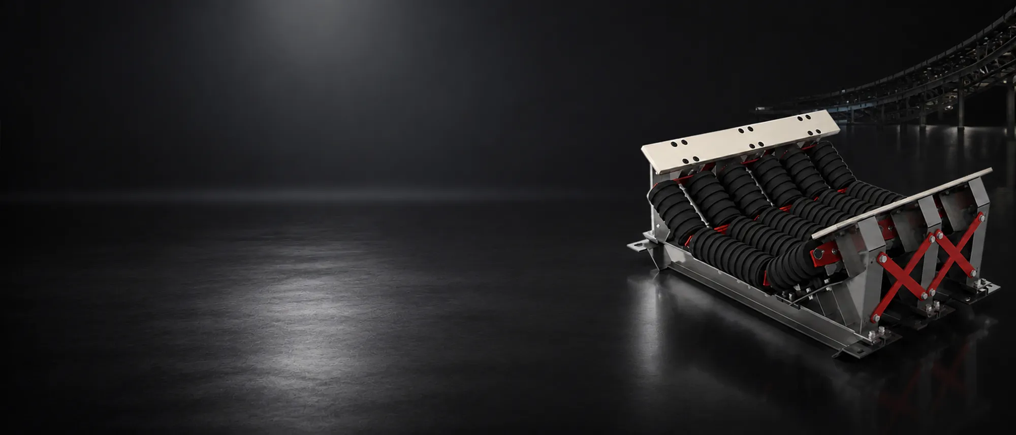
At the load zone, falling material impacts the belt, off-centre loading unbalances it, and the belt sags between idlers — and every component downstream inherits the result. Tru-Trac impact beds absorb that energy and hold the belt flat across the loading length.
01 / Engineering logic
Tru-Trac specifies load-zone equipment around three control objectives, in sequence.
02 / Dynamic Impact Bed architecture
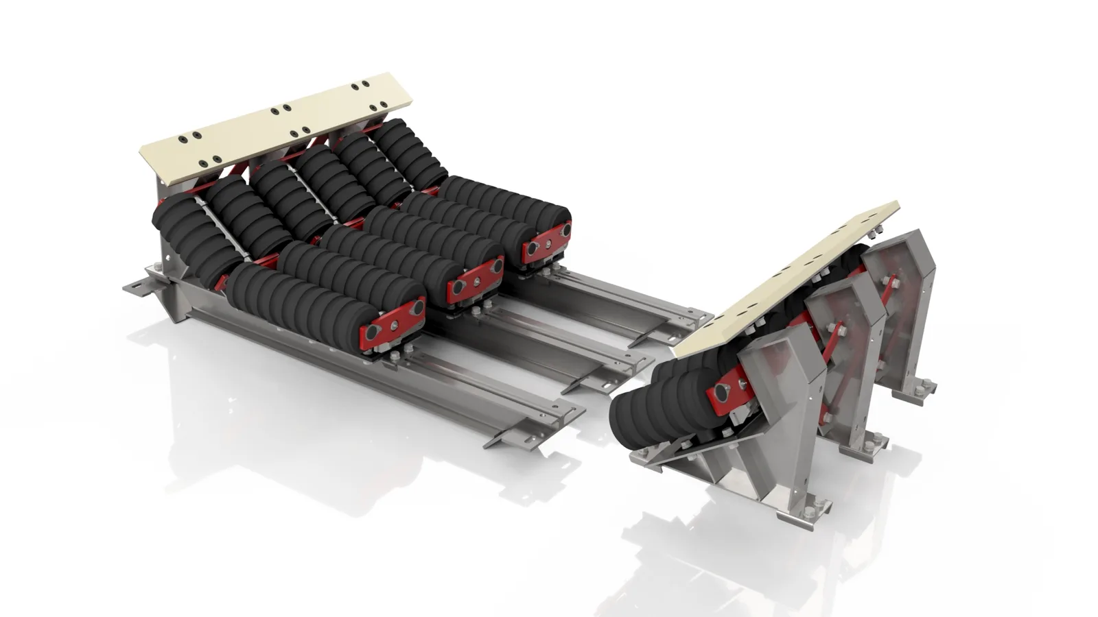
The Dynamic Impact Bed is built for the hardest load zones — heavy aggregate falling from height. Where a static bed resists the impact, the Dynamic bed absorbs and dissipates it.
03 / The range
Selection is by impact energy — lump weight × drop height — plus belt width, tonnage, trough angle and installation access. Every figure is from the catalogue; engineering confirms the final specification.
Impact beds & trough frames
Adjustable Impact Bed
Length: 650 mm bed; install multiple in succession for longer load zones.
- Belt widths: all.
- Adjustable troughing angle for optimal sealing — minimises dust and spillage.
- Slider modular design for simplified installation and maintenance; quick access and fast replacement of worn impact pads.
- Impact bars: UHMWPE top layer, cushioning middle layer, secure pad-fastening bottom layer.
- Electro-galvanised frame for corrosion resistance.
Slider Impact Bed
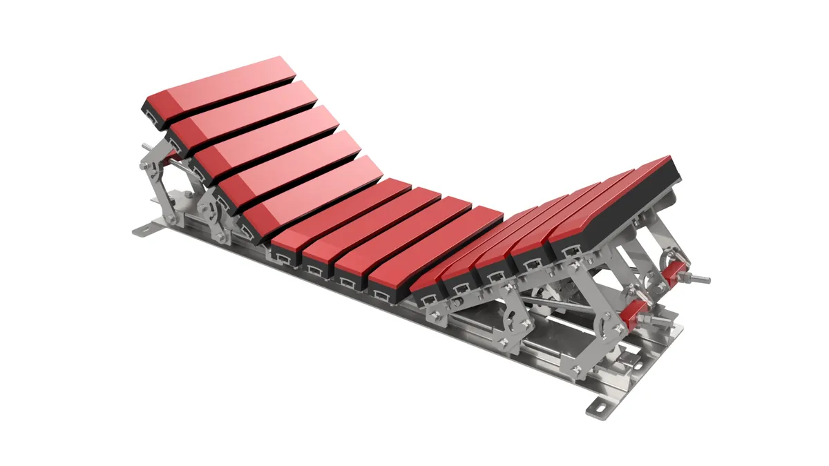
Length: 650 mm bed; install multiple consecutively.
- Belt widths: all.
- Modular design for easy installation and maintenance; quick replacement of worn beds.
- Impact bars: UHMWPE top layer for smooth belt gliding, rubber middle layer for impact cushioning, lower layer for pad fastening.
- Electro-galvanised frame for corrosion protection.
- Improved sealing when skirting rubber is installed on top.
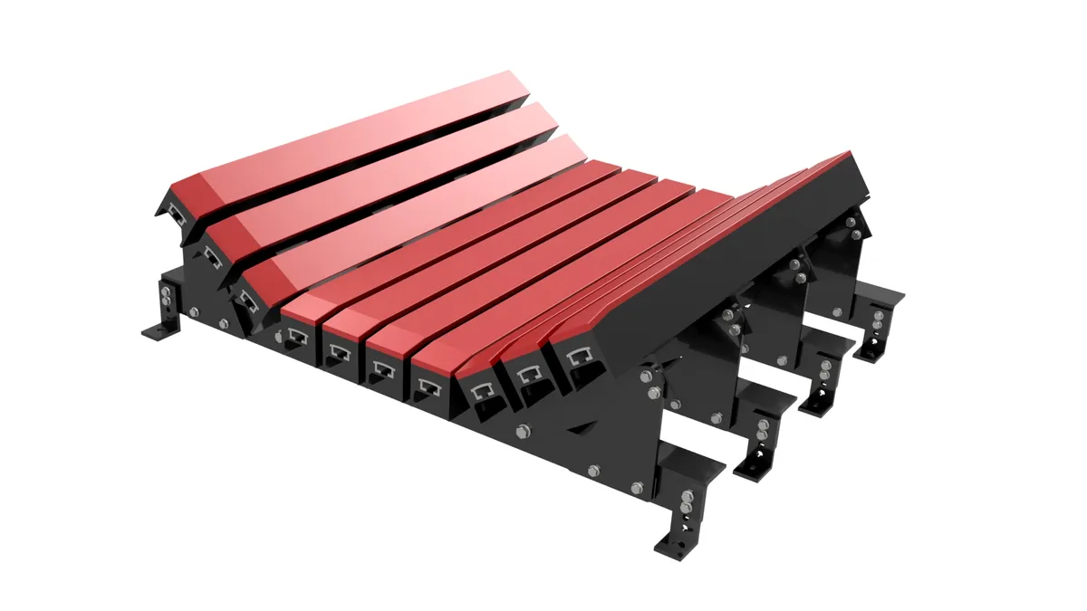
Standard Impact Bed
Length: 1300 mm; available in all belt widths.
- Medium and heavy-duty frames.
- Adjustable troughing angle.
- Entire frame painted for corrosion protection.
- Cost-effective impact protection for typical loading conditions.
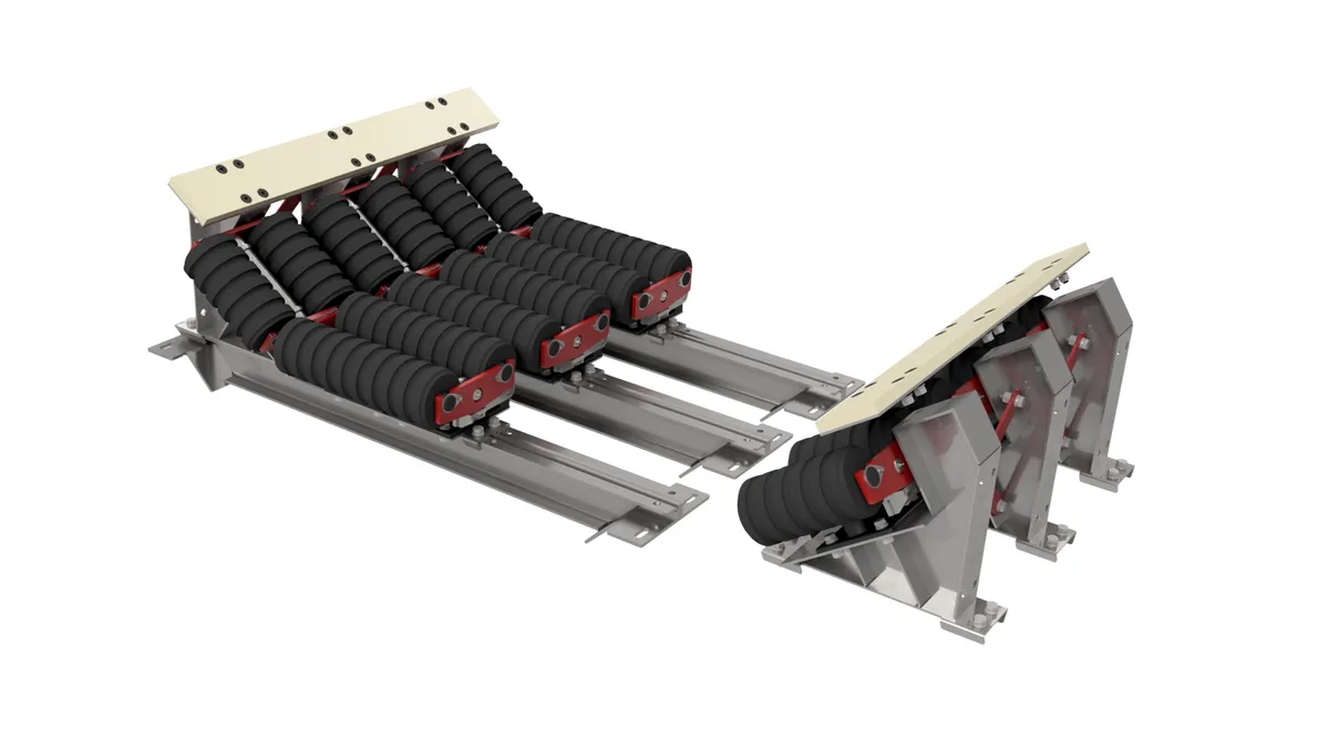
Dynamic Impact Bed
Length: 1300 mm; available in all belt widths.
- Medium and heavy-duty frames.
- Designed to absorb heavy aggregates falling from 3.5–10 m.
- Maximum shock absorption; reduces the velocity of falling rock; supports the belt and maintains skirt sealing.
- Adjustable troughing angle; painted frame for corrosion protection.
Slide and Roll Impact Bed
Max belt speed: 5 m/s.
- Temperature range: −40 °C to 82 °C.
- Materials: UHMWPE, rubber and aluminium.
- Belt widths: all; available in varied bed lengths and roll types.
- UHMW slider bars with high-performance impact rollers — an effective seal with minimised belt drag.
- Wing panels adjustable 15°–60° trough angle; removable troughs for easy maintenance.
- Prevents belt sag; controls spillage and dust at load points.
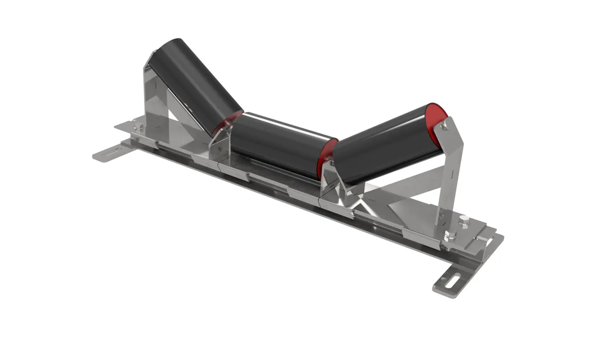
Slider Trough Frames
Sliding mechanism changes troughing rolls without lifting the belt or removing adjacent idler frames.
- Compact inline design for tight or confined spaces; can be installed under loading chutes.
- Electro-galvanised frame for corrosion protection.
- Customised to fit any manufacturer's rollers; compatible with all idlers and impact idlers.
Send us the load condition — lump size, drop height, tonnage, trough angle and access — and we'll specify the right impact-zone architecture.